For my final project, I started with an interest in eye-motion as a form of input, and after looking around a bit, I came across the eye-writer project, which was an initiative set forth to help bring an affordable means of eye-control as a form of communication to those who are otherwise paralyzed:
This left the question of what physical medium I'd be able to incorporate into all of this, and after plenty of deliberation, I decided I'd try and start with something small and simple, such as a servo-mounted laser pointer, which would ideally point in the direction that the user was looking at, based on values taken from the eye-writer software.
In the end I was able to get the eyewriter together and functioning, as well as the laser, as shown in the videos below:
One drawback to the eyewriter is that the user isn't really able to move his or her head, as it throws the calibration(shown below) totally off. The tracker is calibrated by making the user look at an array of points on the screen or surface that will be being used, and interpolates the corresponding eye motions, so that the cursor can move smoothly in response to the eye. Thus, if the user even slightly moves his or her head, the eye is moved to a new baseline position so to speak, and can't use the previously calibrated values. I figured that one interesting way around this might be to mount the laser (which would be acting in place of the on-screen cursor) on to the user's head somehow, thus making it independent of the constraints that the head's position relative to the screen presents, but this was something I didn't get a chance to work on.
What ultimately prevented me from achieving my original goal, was that I ended up being unable to locate the independent interpolated values from within the software, that I could serially send out to the arduino, although I imagine that I should be able to find them if i poke around some more.
I also think that a similar calibration system would need to be implemented, where the laser might point to a series of different points on a given surface, and using those results, the laser could be controlled more precisely.
Friday, May 4, 2012
Mid-Term Documentation
For our Mid-term project, we decided to work on a device that would display info about a user's menstrual cycle, in relation to two input-dates. The idea being that based on a 28-day cycle, a user would input the start date of her cycle, and a future date, and receive an output consisting of the day of her cycle (1 out of 28) that would fall on said future date, as well as a reading of certain hormone levels associated with that day of the cycle. This would be useful for instance, if someone trying to conceive wanted to know whether or not to make certain plans on a certain day.
The difference in days was calculated using the following algorithm:


The difference in days was calculated using the following algorithm:
function g(y,m,d)
m = (m + 9) % 12
y = y - m/10
return 365*y + y/4 - y/100 + y/400 + (m*306 + 5)/10 + ( d - 1 )
g(y2,m2,d2) - g(y1,m1,d1).
This difference in days was then divided by 28 to return the day value, along with its respective hormone values, as outlined in this Data Set. (organized and visualized by kai).


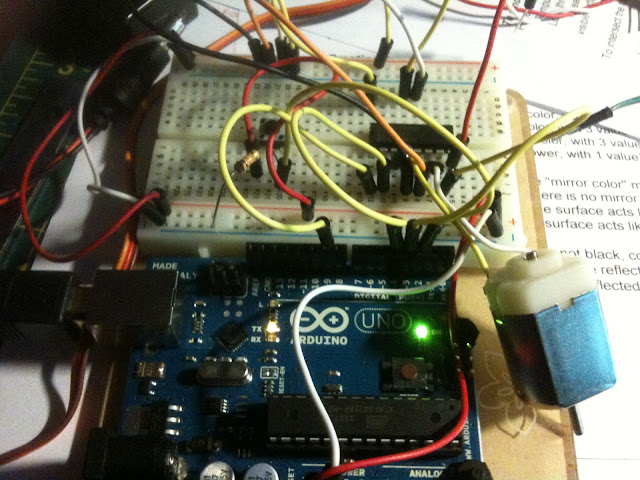
Transistor and H-Bridge
The transistor lab went fairly smoothly.
The H-Bridge on the other gave me a bit of trouble. I'm fairly positive that I had everything wired up properly, especially since I'd rewired it about four times..
using the code from the lab:
const int switchPin = 2; // switch input
const int motor1Pin = 3; // H-bridge leg 1 (pin 2, 1A)
const int motor2Pin = 4; // H-bridge leg 2 (pin 7, 2A)
const int enablePin = 9; // H-bridge enable pin
void setup() {
// set the switch as an input:
pinMode(switchPin, INPUT);
// set all the other pins you're using as outputs:
pinMode(motor1Pin, OUTPUT);
pinMode(motor2Pin, OUTPUT);
pinMode(enablePin, OUTPUT);
//pinMode(ledPin, OUTPUT);
Serial.begin(9600);
// set enablePin high so that motor can turn on:
digitalWrite(enablePin, HIGH);
}
void loop() {
// if the switch is high, motor will turn on one direction:
if (digitalRead(switchPin) == HIGH) {
Serial.println("high");
digitalWrite(motor1Pin, LOW); // set leg 1 of the H-bridge low
digitalWrite(motor2Pin, HIGH); // set leg 2 of the H-bridge high
}
// if the switch is low, motor will turn in the other direction:
else {
Serial.println("low");
digitalWrite(motor1Pin, HIGH); // set leg 1 of the H-bridge high
digitalWrite(motor2Pin, LOW); // set leg 2 of the H-bridge low
}
}
- I noticed that i was able to get HI and LO responses from the switch, and so the corresponding If conditions should have been executed, and yet the motor remained motionless. I was also sure to check that the motor was still working quite a few times. I'm thinking that something might be wrong with the H-bridge, as it would get incredibly hot any time I'd plug pin 8 to the power source, so I may have plugged something in wrong one of the first times around, and done some damage?

Wednesday, March 7, 2012
Week 6: Serial Output
Done with a 10k pot.
Serial Lab part 2: Duplex - controlling the x and y values of an ellipse with two separate pots (analogue values)
Serial Lab part 2: Duplex - controlling the x and y values of an ellipse with two separate pots (analogue values)
Wednesday, February 22, 2012
Week 4: Analog input
LED blinking relative to potentiometer resistance.
FSR leds
Fantasy Device:
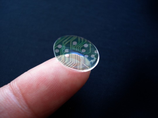
Contact Lens HUD
Something I'd like to see would be some sort of contact lens that would use some kind of micro (or nano?) computing interface as well as a physical interface that might track eye movement as an input and project various data over what a person would normally see without impeding vision (the projections might be transparent for example). I imagine that by using something like augmented reality, these could be used to project data pertaining to certain physical locations, etc.
Something I'd like to see would be some sort of contact lens that would use some kind of micro (or nano?) computing interface as well as a physical interface that might track eye movement as an input and project various data over what a person would normally see without impeding vision (the projections might be transparent for example). I imagine that by using something like augmented reality, these could be used to project data pertaining to certain physical locations, etc.
Sensors encountered over the past week:
Most of the sensors that i took notice of were ones that I directly interacted with, some were even hard to distinguish due to being so acclimated to using them.
card readers - atm, nyu building turnstiles, subway turnstiles, metrocard machines.
pushbuttons- soda machine, atm, laptop keys, camera shutter release, crosswalk button, doorbell
touch-interfaces - phone, atm, smartboard, metrocard machine, creditcard machine.
motion-sensitive - sliding doors, lights in batrhoom
Wednesday, February 15, 2012
Week 3: Digital something or other.
Working Switch
Creative design
Code:
const int left = 2;
const int right = 3;
const int up =4;
const int down = 5;
const int a =6;
const int b =7;
const int red =13;
const int green =12;
const int blue =11;
int L;
int R;
int U;
int D;
int A;
int B;
int len;
String input;
String temp;
String code = "uuddlrlrba";
//run this once
void setup(){
Serial.begin(9600);
pinMode(left,INPUT);
pinMode(right,INPUT);
pinMode(up,INPUT);
pinMode(down,INPUT);
pinMode(a,INPUT);
pinMode(b,INPUT);
pinMode(red,OUTPUT);
pinMode(green,OUTPUT);
pinMode(blue,OUTPUT);
input="";
}
void loop(){
len = input.length();
digitalWrite(green,LOW);
digitalWrite(red,LOW);
digitalWrite(blue,LOW);
L = digitalRead(left);
R = digitalRead(right);
U = digitalRead(up);
D = digitalRead(down);
A = digitalRead(a);
B = digitalRead(b);
if(U==HIGH){
digitalWrite(red,HIGH);
delay(250);
temp+= 'u';
}
else if(D==HIGH){
digitalWrite(red,HIGH);
delay(250);
temp+= 'd';
}
else if(L==HIGH){
digitalWrite(red,HIGH);
delay(250);
temp+= 'l';
}
else if(R==HIGH){
digitalWrite(red,HIGH);
delay(250);
temp+= 'r';
}
else if(A==HIGH){
digitalWrite(red,HIGH);
delay(250);
temp+= 'a';
}
else if(B==HIGH){
digitalWrite(red,HIGH);
delay(250);
temp+= 'b';
}
if(temp.compareTo("")!=0){
input +=temp.charAt(0);
Serial.println("check");
temp="";
}
if(input.compareTo(code)==0){
digitalWrite(blue, HIGH);
}
Serial.println(input);
Wednesday, February 8, 2012
Week 2: Circuits and switches and labs, oh my.
I'm glad to report that everything went well for the most part.

Soldering was a breeze, although I should probably pick up a roll or two of black and red wire, so that I won't have to clip anymore of breadboard wires.


Soldering was a breeze, although I should probably pick up a roll or two of black and red wire, so that I won't have to clip anymore of breadboard wires.
Here we have a a regulator hooked up to a 9-volt battery, with a resulting output of just about 5v.

Two diodes in series with a resistor and a button switch.
Lastly, My switch: I made a board with alternating strips of aluminum tape. There are two sets of strips, where every other strip belongs to a set. The first set closes the circuit to one diode, and the second closes the circuit to the other. When the stylus makes contact with either strip, it closes to circuit to its respective diode, and when it is run across the alternating strips, the diodes alternate.
Subscribe to:
Posts (Atom)